UK to Antarctica with a Homemade Radio Beacon
TL;DR I built a crude, low-power radio beacon and put it on a hill. A research station in Antarctica received my signal.
Background
Radio operators can communicate over vast distances using the HF band, which is typically defined as frequencies between 3MHz and 30MHz. Radio waves at these frequencies can be refracted by layers in the ionosphere - some 200-400km above the Earth’s surface - such that they can skip over terrain and travel beyond the horizon. The longest distances are achieved by multiple “hops”; transmitted signals can be refracted back down to the earth’s surface by the ionosphere, then reflected back up again by the ground (or perhaps sea water), refracted down again in the ionosphere, and so on.

Fig. 1 - Illustration of inter-continental HF propagation [1]
Ionospheric propagation is affected by a complex combination of factors, including the season, time of day at the sites of both the transmitter and receiver, solar activity, the current point in the 11-year solar cycle, and many other factors. Although the science of predicting HF propagation is quite advanced, practical testing of propagation paths with WSPR beacons provides valuable insight.
What is WSPR?
Weak Signal Propagation Reporter (WSPR, pronounced “whisper”) is a radio protocol used in testing propagation paths. WSPR beacons transmit digital signals at very low power levels, often less than 1 Watt. The broadcast messages simply include the beacon operator’s callsign, the beacon’s location (coded with the Maidenhead Locator System), and the transmit power.
A large and dispersed global network of receivers listen for WSPR signals. They decode received WSPR signals and report information such as the transmitter and receiver locations and callsigns to an online database called WSPRNet. Radio operators can log in to WSPRNet to visualise propagation paths across the world.
Project Aims
As I operate my portable HF radio from various remote locations, I wanted a WSPR beacon so that I could monitor propagation paths from these locations, over extended time periods. I also liked the idea of contributing WSPR data for the benefit of the wider amateur radio community.
Although I could have bought a “ready-made” WSPR beacon, designing and building my own felt more in keeping with the spirit of amateur radio. My main requirements for the WSPR beacon were:
-
I must be able to leave the beacon unattended on a remote hilltop to make periodic transmissions over several days. The device should therefore be easily portable, able to operate autonomously, have low power consumption, and be weatherproof.
-
As each HF band has its own characteristics, the beacon should support testing propagation in a range of HF bands (e.g. 10m, 15m, 20m, 40m).
-
Accurate timing and frequency of transmissions. The WSPR protocol has specific timing requirements that must be observed for successful communication. To avoid causing interference to other users of the RF spectrum, it’s also crucial that beacon always maintains frequency accurately, despite variations in temperature (and other factors) that may cause RF oscillators to drift.
-
Low cost. This project was just a bit of fun, so I didn’t want to spend too much money on it. Ideally the cost of materials would be less than £100.
-
Short development/build time. With limited time to devote to the project, I wouldn’t try to achieve engineering perfection. It was perfectly acceptable for the device hardware and firmware to be a bit “lashed together”!
Hardware Overview
![]()
Fig. 2 - Block diagram of main hardware components
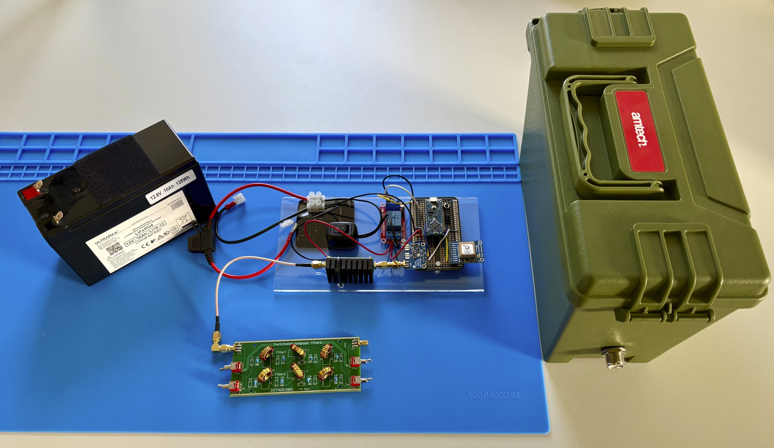
The principal hardware components of the beacon are:
-
Arduino Nano Every. This Arduino board is based on the ATMega4809 microcontroller and acts as the central coordinator/”brain” of the beacon. Its firmware implements the beacon’s main functionality, and it communicates with and controls the other hardware modules.
-
GPS module. This module receives signals from the GPS and GLONASS satellite constellations and provides location and time information to the microcontroller. Importantly, it also has a “one-pulse-per-second” (1PPS) output, which provides a very accurate timing signal to the microcontroller. This 1PPS signal is used by the microcontroller to measure the clock generator’s frequency error precisely.
-
SI5351 clock generator. This module generates the beacon’s RF signal. The microcontroller sends commands to the clock generator to control and modulate the output frequency. A second output of the clock generator is set to produce a fixed-frequency reference signal, which together with the 1PPS signal from the GPS module, is used by the microcontroller to estimate the clock generator’s frequency error.
-
RF power amplifier. The clock generator’s output signal power is amplified to about 2 Watts, using a low-cost broadband RF power amplifier.
-
Relay module. The relay module enables the microcontroller to switch on/off the 12V power supply to the RF power amplifier, saving power between transmissions.
-
RF filters. The output of the clock generator is a square wave - a signal containing undesirable harmonics that could cause interference in other bands across the RF spectrum. The RF low-pass filters perform the crucial role of removing the harmonics.
-
Battery. A 12V LiFePO4 battery with a capacity of 10Ah was selected. This is adequate to power the beacon for about a week. LiFePO4 batteries are lighter and more portable than equivalent lead acid batteries, but more expensive.
The components were mounted in a water-tight plastic box, with a hole drilled for a bulkhead SO-239 antenna connector.
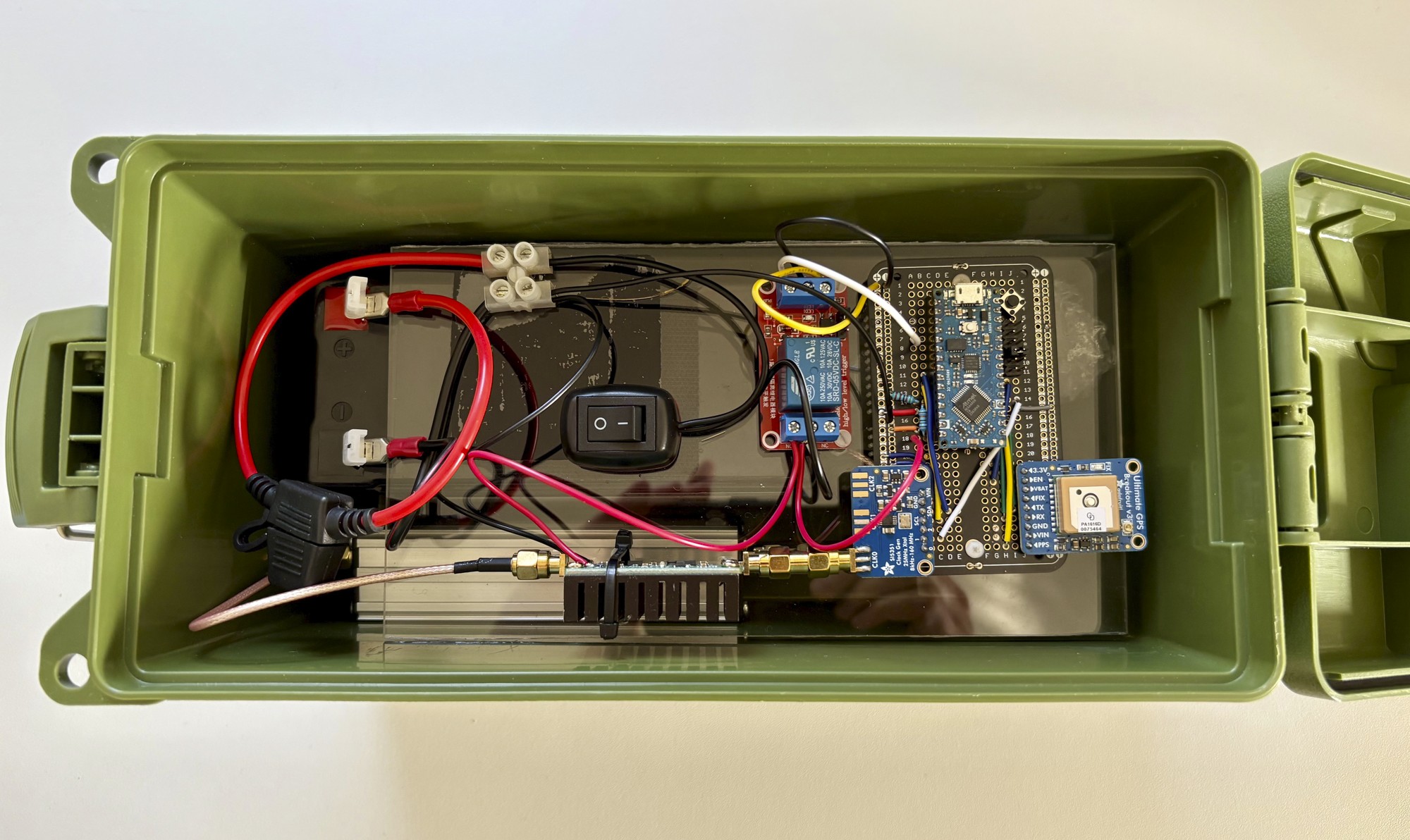
Fig. 3 - Hardware components mounted in a plastic enclosure
Firmware Overview
Although source code for many other Arduino-based WSPR beacons is freely available, I thought I might learn more about Arduino and its ecosystem by developing my own firmware. I have shared my source code in my wspr-beacon GitHub repository, just in case it’s useful to others. It makes use of several “mature” libraries, including: JTencode, si5351Arduino and TinyGPSPlus.
Features of the firmware include:
-
Automatic generation of the Maidenhead locator according to the geographic position of the beacon.
-
Using the GPS-derived time to ensure correct timing of transmissions, according to the requirements of the WSPR protocol.
-
Frequency counter functionality that accurately measures the SI5351 clock generator’s frequency error. Clock cycles of a reference signal from the SI5351 are counted over a very precise (timed using the GPS module’s 1PPS) 10 second time window, and compared to the expected number of clock cycles. The measured frequency error is then corrected with fine calibration of the SI5351. This frequency correction process happens immediately before every transmission, so that frequency drift is minimised.
-
Reading the state of jumpers on the circuit board, to set the desired HF band (10m, 15m, 20m, 40m) for transmission, and the time period between transmissions.
Deployment
I carried my WSPR beacon and M1ECC Slidewinder DX vertical antenna to the top of a hill. After tuning the antenna to be resonant on the 20m HF band, I connected it to the beacon, and switched on the power… a few minutes later, the first reports of my beacon started to appear on WSPRNet! I left the beacon running for a day and it was heard all around the world.
![]()
Fig. 4 - Photo of beacon deployed on a hill in the UK
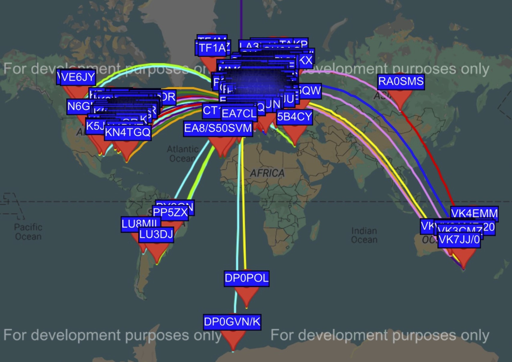
Fig. 5 - WSPRNet map showing stations that received the beacon’s signal
One particular station that received my WSPR signal caught my eye: DP0GVN. This callsign belongs to an amateur radio club station located at the German Antarctic Research Station “Neumayer III”, located on the Ekstrom Ice Shelf in Antarctica! Furthermore the German icebreaker ship RV Polarstern (callsign DP0POL) reported my WSPR signal as it headed towards the Southern Ocean. It felt quite satisfying that my beacon had been heard in such remote places!
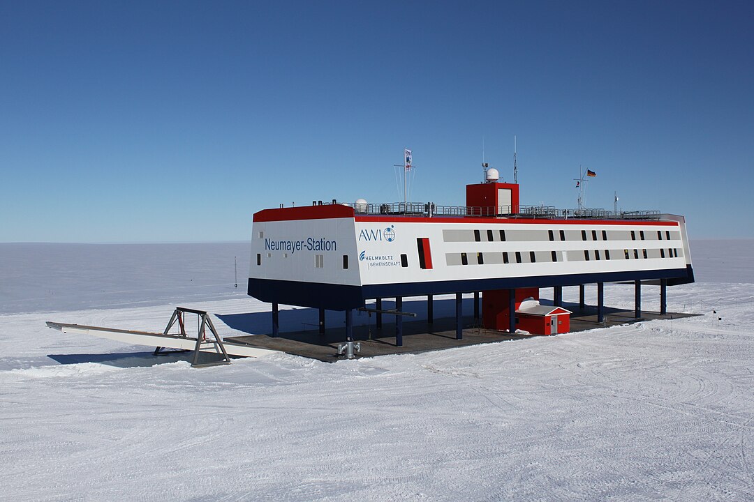
Fig. 6 - Photo of Neumayer Station, Antarctica [2]

Fig. 7 - Photo of RV Polarstern [3]
Further Development
There are many technical improvements that could be made to the WSPR beacon, including:
-
Improved power management. Some microcontrollers have power-conserving “sleep modes” that could be utilised in the long periods between WSPR transmissions. Porting my firmware to such a device could lower power consumption drastically, perhaps extending the battery life to a period of several months. Intelligent power management of the GPS module, together with use of a more efficient RF power amplifier, could also improve battery life significantly.
-
Automatic switching of RF filters. With the current design, the RF filters must be manually switched when changing between different HF bands. This switching could be automated, so that the beacon could transmit across multiple bands without manual intervention.
-
Reduced size. There is a lot of scope to reduce the physical size of the beacon, so that it would be even more easily portable.
Credits
[1] Diagram by Khesus99 - Own work, CC BY-SA 4.0, https://commons.wikimedia.org/w/index.php?curid=101239953
[2] Image by Felix Riess - Own work, CC BY-SA 3.0 de, https://commons.wikimedia.org/w/index.php?curid=25468109
[3] Image by Hannes Grobe, Alfred Wegener Institute - Self-published work, CC BY-SA 2.5, https://commons.wikimedia.org/w/index.php?curid=731714